

Top Fiber Testing Equipment for Network Teams
A fiber link can look complete on a rack diagram and still introduce loss, intermittent errors, or costly rework. Selecting the top fiber testing equipment is therefore not about acquiring the most instruments. It is about giving network teams the right evidence at each stage of the fiber lifecycle: clean connector end faces, verified installation quality, fast fault isolation, and records that stand up to customer, compliance, and operational review.
For enterprise networks, data centers, campuses, healthcare facilities, industrial sites, and service-provider handoffs, the best toolkit usually combines several test methods. Each answers a different question. A visual fault locator can reveal a gross break, but it cannot certify a link. An OTDR can locate a reflective event, but it does not replace insertion-loss testing. Teams that understand those boundaries make better purchasing decisions and resolve issues with far less guesswork.
What Top Fiber Testing Equipment Must Cover
Fiber testing requirements begin with the work being performed. A contractor certifying new backbone cabling has different needs than an IT team troubleshooting an unstable uplink. A data center operator managing parallel-optics links also needs different capabilities than a facilities team maintaining a small single-mode campus backbone.
The most effective fiber test strategy covers four areas: inspection, certification, characterization, and troubleshooting. These functions can overlap, but they should not be treated as interchangeable.
Connector inspection and cleaning
Contaminated end faces remain one of the most common and preventable causes of fiber performance issues. Dust, oil, residue, or scratches can increase insertion loss, create reflections, and damage a mating connector. A fiber inspection scope or video probe lets technicians inspect the ferrule before connection and document whether it passes a defined cleanliness standard.
Inspection should be paired with proper cleaning tools and a repeatable process: inspect, clean when needed, then inspect again. This is a relatively modest investment compared with the time lost chasing faults caused by a contaminated connector. For high-density environments using MPO/MTP connectors, inspection tools that clearly assess multiple fibers become especially valuable.
Optical loss test sets for certification
An optical loss test set, commonly called an OLTS, measures end-to-end insertion loss and optical return loss where required. This is the primary tool for certifying whether an installed link meets its intended performance standard. It can also measure length and verify fiber continuity, depending on the platform and test configuration.
For new installations, OLTS testing provides the most meaningful pass/fail result because it measures the entire channel in the same direction that network traffic travels. Proper reference-setting is essential. Poor reference practices can make a failing link appear acceptable or create inaccurate results that complicate acceptance testing.
Bi-directional loss testing deserves particular attention. Because connectors and splices can behave differently by direction, averaging results from both ends gives a more accurate representation of link loss. It takes additional time, but the added confidence is often justified for critical single-mode links, high-speed applications, and projects with formal documentation requirements.
OTDRs for fiber characterization and fault location
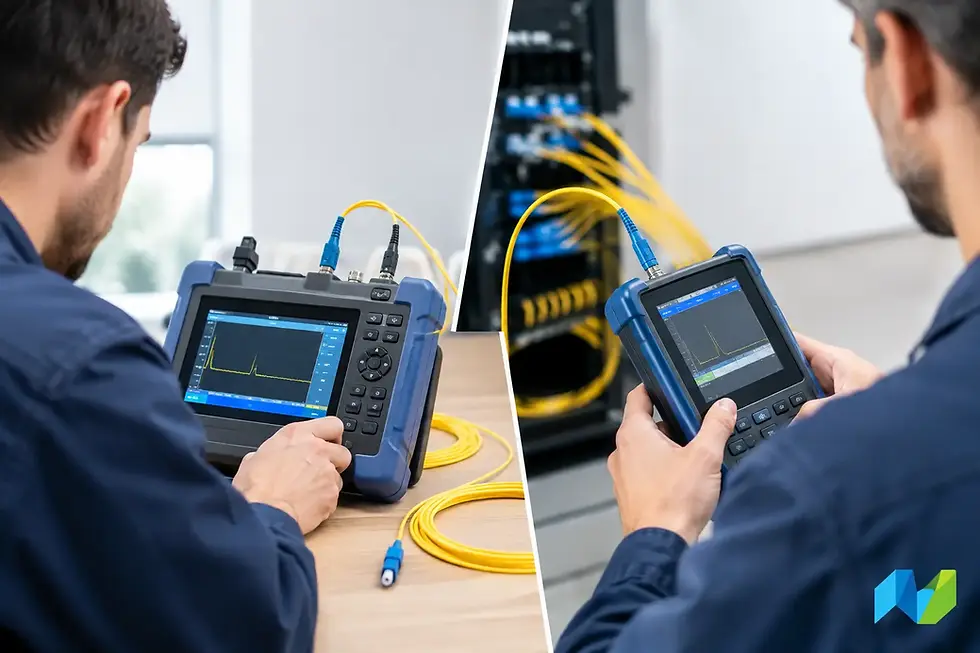
An optical time-domain reflectometer, or OTDR, sends light pulses into a fiber and analyzes the returned signal. The resulting trace helps technicians locate events such as connectors, splices, bends, breaks, and areas of excessive reflection. It is the essential instrument when a link fails and the question is not simply whether there is loss, but where that loss originates.
OTDRs are especially useful on longer runs, outside-plant fiber, campus backbones, and single-mode links. They also provide value during construction by documenting splice quality and identifying events before the cable is placed into service.
However, OTDR results require interpretation. Launch and receive fibers are necessary to view connections at both ends of the link, and dead zones can obscure closely spaced events. An OTDR may identify a suspicious event, but it does not always establish overall channel compliance. For that reason, it works best alongside an OLTS rather than in place of one.
Visual fault locators for fast physical checks
A visual fault locator, or VFL, emits visible red light through a fiber. It is practical for tracing fibers, identifying severe bends, locating breaks over short distances, and confirming continuity during moves, adds, and changes. It is simple, portable, and useful in the field.
Its limitations are equally clear. A VFL cannot measure loss, validate a high-speed link, or replace formal certification. Teams should consider it a fast diagnostic accessory, not a complete fiber test solution.
Choosing Equipment by Fiber Environment
The right purchase depends on fiber type, link architecture, test volume, and the consequences of downtime. A small enterprise with occasional fiber moves may prioritize an inspection probe, cleaning kit, VFL, and access to an OTDR when complex faults arise. A cabling contractor or systems integrator performing recurring installations needs an OLTS with automated standards-based certification and professional reporting.
Data center teams should look closely at support for multimode and single-mode fiber, high-density MPO/MTP connectivity, polarity verification, and documentation workflows. As speeds increase to 40G, 100G, 400G, and beyond, loss budgets become less forgiving. A test platform that supports the connector types and link configurations in use can prevent a costly mismatch between installed cabling and active optics.
For large campuses and distributed facilities, portability and battery life matter, but so do centralized result management and consistent test procedures. A tool that produces dependable reports helps infrastructure managers compare installers, validate warranty submissions, and maintain a usable record of the physical layer over time.
Features That Improve Field Results
The most advanced instrument is not always the best fit if it creates friction in the field. Network teams should assess how quickly technicians can configure common tests, whether standards and limits are built into the workflow, and how easily results can be reviewed by customers or internal stakeholders.
Look for equipment that supports clear pass/fail guidance, configurable test limits, trace storage, exportable reporting, and repeatable naming conventions. Automated workflows reduce configuration errors, particularly when multiple technicians or contractors are involved. They also make it easier to enforce consistent testing across locations.
Interchangeable adapters are another practical consideration. The tester must support the connectors and fiber types present in the environment, including LC, SC, and MPO/MTP interfaces where applicable. Buying an instrument without accounting for required launch cords, reference cords, adapters, and cleaning supplies can delay deployment and compromise measurement quality.
Training has a direct effect on the value of the equipment. An OTDR trace is only useful when the operator understands pulse width, range, index of refraction, event tables, and dead zones. Similarly, an OLTS result is meaningful only when reference methods and test limits are selected correctly. The best technology purchase includes a plan for onboarding, procedure development, and support when unusual results appear.
Build a Testing Workflow, Not Just a Tool List
Reliable fiber validation starts before a technician connects a tester. Confirm the link design, fiber type, connector type, expected length, required standard, and applicable loss budget. Then inspect and clean every mating surface before testing. This sequence prevents contaminated connectors from producing misleading results or damaging otherwise clean interfaces.
For installation acceptance, use an OLTS to certify end-to-end loss and document the outcome. Use an OTDR when a loss result fails, when characterizing longer links, or when the project requires event-level evidence. Keep VFLs available for quick continuity and tracing work, particularly during patching changes and first-response troubleshooting.
Documentation should be treated as part of the deliverable. A labeled test result tied to a rack, panel, fiber ID, and date saves time months later when a circuit is upgraded or a fault emerges. Consistent records also help teams identify recurring issues, such as a problematic pathway, installation practice, or connector type.
A Practical Investment for Network Reliability
The top fiber testing equipment is not defined by a single instrument or brand. It is a coordinated set of tools selected for the work your team performs, supported by sound procedures and technicians who know how to interpret the results. The trade-off is straightforward: buying only for the immediate problem can reduce upfront cost, while investing in certification, characterization, and inspection capabilities reduces uncertainty over the life of the network.
Advanced Network Devices Inc. helps organizations evaluate fiber testing approaches against their actual infrastructure, operational requirements, and reporting expectations. The useful next step is to review a representative group of links - not just the simplest ones - and define the evidence your team needs to confidently place each circuit into service.


Comments