
Fiber Certification vs OTDR Testing Explained
A newly installed fiber link can carry traffic and still fail the requirements for the application it was built to support. That is the practical distinction behind fiber certification vs OTDR testing: one process verifies that a link meets defined performance limits, while the other reveals what is happening along the length of that link. Both are valuable, but they answer different questions.
For IT leaders, network engineers, and cabling contractors, choosing the wrong test method can create avoidable risk. An OTDR trace may look clean while total insertion loss exceeds the channel budget. Conversely, a certification test may identify excessive loss without showing which splice, connector, bend, or damaged section caused it. A reliable fiber validation strategy recognizes the role of each tool and uses the right evidence for the job.
Fiber Certification vs OTDR Testing: The Core Difference
Fiber certification is an acceptance test. It determines whether a permanent link or channel passes the loss, length, polarity, and other requirements defined by the selected standard and application. Most certification workflows use an optical loss test set, often called an OLTS, to measure end-to-end insertion loss at the required wavelengths. The tester compares the measured results against the applicable limit and generates a pass or fail result with documentation.
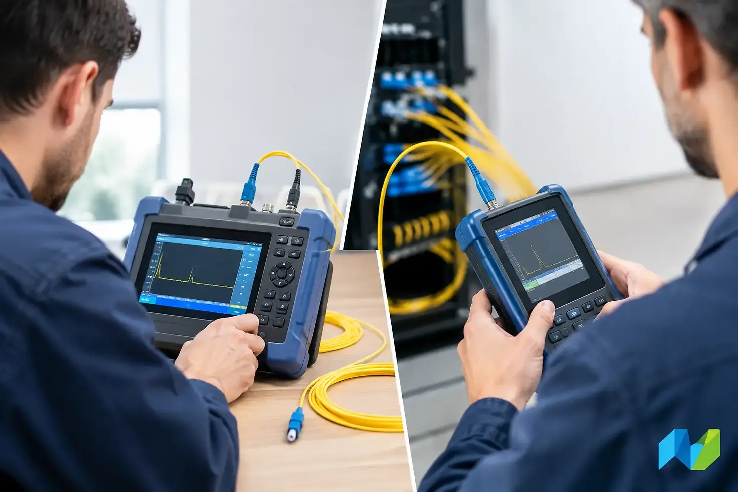
OTDR testing is a diagnostic and characterization process. An optical time-domain reflectometer sends pulses of light into the fiber and analyzes the reflected light returning to the instrument. The result is a trace that estimates fiber length, attenuation, reflective events, non-reflective events, splice loss, and event location.
Put simply, certification answers, “Is this link acceptable for its intended use?” OTDR testing answers, “Where is the loss or event located, and what may be causing it?” Neither result replaces the other.
What Fiber Certification Measures
A fiber certifier measures the complete optical path from one end of the link to the other. Depending on the test configuration and standard, it can validate insertion loss at wavelengths such as 850 nm and 1300 nm for multimode fiber, or 1310 nm and 1550 nm for single-mode fiber. It may also document length, polarity, and the test limits used.
The critical result is insertion loss. Every connector, splice, adapter, and section of fiber contributes to the total loss budget. A link can be functional when tested with low-speed electronics but still have insufficient margin for a higher-speed transceiver, a longer-distance application, or future moves, adds, and changes. Certification verifies that the installed infrastructure meets the agreed-upon performance requirement before it becomes a production dependency.
A proper certification workflow also produces consistent records. Automated testers can store test parameters, pass or fail outcomes, reference settings, and traceable identifiers for each link. That documentation is useful during project closeout, warranty discussions, audits, and future troubleshooting. It gives infrastructure teams a baseline instead of forcing them to diagnose a problem without knowing how the link performed on day one.
Certification requirements depend on the installation scope. The correct limit may come from TIA, ISO/IEC, an application standard, a manufacturer warranty program, or a customer specification. The test should be configured to the standard that actually governs the project. A generic loss limit may be better than no test at all, but it is not equivalent to certifying against the correct link model and application target.
What an OTDR Sees That a Certifier Cannot
An OTDR provides event-level visibility. On a long outside-plant single-mode run, it can identify the approximate location of a splice with high loss, a connector with excessive reflectance, a bend, or a suspected fiber break. That capability is especially useful when access points are far apart, fibers are routed through multiple enclosures, or a cable path crosses a campus, warehouse, industrial site, or carrier handoff.
The OTDR trace also provides context that end-to-end loss testing cannot. If a link fails insertion-loss certification, the OLTS confirms the overall loss but does not identify the source. An OTDR can help isolate whether the issue is concentrated at a patch panel, a fusion splice, a particular cassette, or a section of cable.
That said, an OTDR has limits. It operates with dead zones near the launch point and after highly reflective events. Without properly selected launch and receive fibers, the first and last connector events may not be accurately characterized. Pulse width, range, averaging time, refractive index, and event-detection thresholds also affect the trace. A poorly configured OTDR can produce a misleading result or mask an important event.
OTDR measurements are directional as well. A splice may appear to have different loss values when measured from opposite ends because of differences in fiber backscatter characteristics. For high-quality splice analysis, bidirectional testing and averaged results are often necessary. This is one reason an OTDR trace should be interpreted by a trained technician rather than treated as a simple pass or fail screen.
Why an OTDR Alone Does Not Certify a Fiber Link
It is tempting to treat a clean OTDR trace as proof of a good installation. That shortcut is risky. OTDRs estimate loss from backscatter, while an OLTS directly measures end-to-end insertion loss through the complete path. The two methods are related, but they are not interchangeable.
A short structured-cabling link is a common example. Multiple connector pairs may add enough cumulative loss to fail the applicable channel limit, yet the events can be difficult for an OTDR to resolve because they are closely spaced. An OTDR may also miss the practical impact of dirty end faces at the test connection or inconsistently mated connectors. Direct insertion-loss testing is the appropriate basis for acceptance.
For the same reason, a passing OTDR event table does not necessarily validate polarity. In duplex fiber systems, the transmit path must reach the correct receive path. Certification workflows can verify the full link configuration, while an OTDR provides no substitute for application-aware polarity validation.
When to Use Each Test Method
The most effective approach is determined by the network type, installation scope, and project requirements. Fiber certification should be the primary acceptance method for enterprise structured cabling, data center links, and any installation that must demonstrate compliance with a defined standard or warranty requirement. It provides the pass or fail evidence procurement teams, facilities groups, and infrastructure owners need.
OTDR testing is particularly valuable for long single-mode links, outside-plant fiber, backbone routes, and repair work. It becomes essential when a team needs to locate a fault without opening every enclosure or tracing every segment manually. It is also useful as supplemental documentation for new fiber builds where splice quality, reflectance, and event location matter.
For many projects, the correct answer is not certification or OTDR testing. It is certification first, supported by OTDR testing where characterization or fault isolation adds value. A practical workflow is to inspect and clean every connector, establish correct reference conditions, certify each fiber at the required wavelengths, then use OTDR testing to investigate failures or document longer and more complex routes.
Building a Defensible Fiber Test Strategy
A dependable test plan begins before technicians arrive on site. Define whether the project is testing permanent links or channels, identify the governing standard, confirm the fiber type and connector architecture, and set the required wavelengths and loss limits. These details determine the instrument configuration and the documentation expected at closeout.
Teams should also plan for test quality, not just test completion. Connector inspection and cleaning are fundamental because contaminated end faces are among the most common causes of unexpected loss and reflectance. Reference cords, launch cables, adapters, and test ports must be maintained and matched to the connector types in use. Even capable instruments cannot compensate for poor test discipline.
Reporting should be treated as a project deliverable. A useful report ties each result to a cable ID, location, fiber number, test direction, wavelength, standard, and pass or fail status. When OTDR traces are included, event tables and trace files should be retained with the certification records. That package turns test data into an operational asset for the people who will support the network years after installation.
Tool selection matters as well. A basic light source and power meter can measure loss, but a dedicated certification platform improves repeatability, automates limit selection, and simplifies reporting at scale. An OTDR should provide the dynamic range, event resolution, wavelengths, and reporting capabilities appropriate for the fiber environment. Advanced Network Devices helps organizations align fiber test platforms with the standards, workflows, and support requirements behind their infrastructure programs.
The best fiber test result is not merely a green screen at project closeout. It is a trustworthy record that confirms the link can support the intended application and gives the operations team a clear starting point when conditions change.


Comments